By Steve Wood, Senior Trainer and Assessor, CERTLOC
In our previous article, “The Signal: Edition 2,” we explored the creation of the signal by applying a voltage to the target and enabling the voltage to travel back to the transmitter, establishing current flow and generating the electromagnetic field we detect. However, an important question arises: “How does the voltage leave an insulated copper cable or a coated gas or water main?”
Far End Earthing
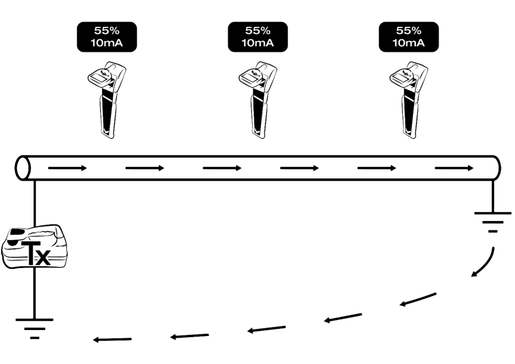
The optimal method is through Far End Earthing, where the end of the target is connected to the earth/ground. Here, the voltage and current travel to the end of the target, then into the ground, and back to the source. This method ensures a stronger and more consistent signal along the target line. Unfortunately, most targets are not far end earthed. One interesting exception is electrical cables due to the Multiple Earthed Neutral (M.E.N.) system, which we will address in another edition.

Capacitance
More commonly, current and voltage flow due to Capacitance. A capacitor charges up with electricity and discharges rapidly. When something conductive is insulated and buried in the ground, it becomes a capacitor. Thus, the voltage and current discharge into the ground as they travel along the target. The efficiency of this process depends on two key factors: the length buried in the ground and the amount of conductive material inside the target.
For instance, a 400-pair Telstra copper cable provides a better signal than a 10-pair cable. If you’ve ever placed an induction clamp around a 2-pair lead into a house from a pit, you likely experienced no signal at all or possibly a very weak signal due to the minimal copper content and the lack of earthing at the house. To overcome this, move the clamp further away or, ideally, use Direct Connect to the target.

Practical Considerations
- Induction Clamp and Capacitance: The signal travels equally in both directions from the clamp. If you experience no or poor signal, the target is likely cut or ends close to the clamp’s position.
- Direct Connect: This method ensures the signal travels from one end outward, making it the preferred connection method.
- Alternating Current (AC) vs. Direct Current (DC): We use AC because it can pass through a capacitor, while DC cannot.
- Signal Dissipation: The signal dissipates proportionally to the target’s length. Thus, the longer the target, the slower the signal reduction.
- Traceable Rods: These rely on capacitance, so insert as much rod as possible to improve the signal. Consider Far End Earthing the rod if it can reach another pit, significantly enhancing the signal.
- Frequency Adjustment: Increasing the frequency can help but be cautious of potential issues like signal distortion or mutual induction, leading to ghosting on nearby conductive assets.
Conclusion
Understanding the roles of capacitance and far end earthing is vital for Certified Locators to achieve accurate and reliable results. Each method has its nuances, and applying the right techniques can significantly improve signal detection and asset location accuracy.
For more insights and technical updates, be sure to look out for the next edition of Technical Tips for Certified Locators. Your feedback, questions, and input are always welcome.